Subj: [HeathKit] HW-16 anti-chirp mod
Date: Sun, Jul 2, 2000 8:26 PM EDT
Updated: December 2012
The Heath HW-16
transceiver's transmitter has a tendency to be chirpy,
even when running crystals
rather than a VFO. I've spent a lot
of hours trying to make my
old HW-16 oscillator unconditionally stable, and
I've about given up. It is just too hard to grid-block key an
oscillator and
get a solid note from a wide
variety of crystals.
As an alternative I've come
up with a "no-new-holes" modification to allow
the operator to select
normal break-in keying OR manual transmit/receive
switching.
With an active crystal or
good drive from a VFO, you can leave the switch in
the "break-in"
position and the transmit/receive switching is automatic as
you send. If you find yourself with a crystal that is
slow to start, and
chirpy, switch to the
"transmit" position. In this
position the receiver is
muted (same as with the key
down in break-in) and the oscillator is turned on
throughout the
transmission. The rest of the
transmitter stages are
grid-block keyed as
usual. The result is the best sounding
signal ever to
radiate from an HW-16.
I've noticed that many
people hate the receiver overload clicks and screeches
associated with the break-in
on this rig anway (they can be reduced by adding
a 0.47uF cap from the base
of Q1 to ground, by the way), so the loss of
break-in is not a big
deal.
To kill these noises most
HW-16 operators tend to reach over and
turn the receiver audio down
while transmitting, defeating the purpose
of break-in anyway. Why not reach over and throw a switch to
choose transmit
or receive mode?
The modification is
simple. Remove the upper crystal socket
and use the two
holes for a mini DPDT switch
and an LED in chrome holder (both from Radio
Shack). No drilling needed and it would be simple to
put the crystal socket
back later.
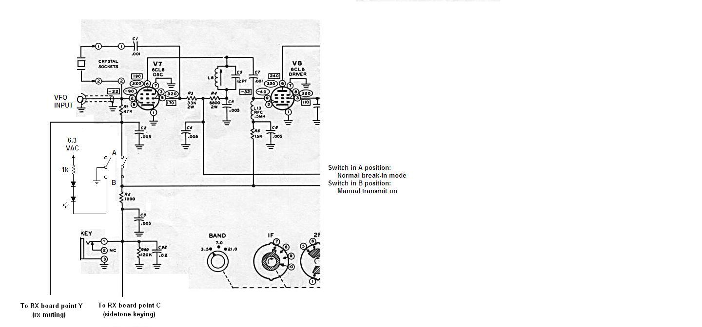
One side of the DPDT switch
is used to interrupt the connection of the 47k
oscillator grid-blocking
resistor R1 to the terminal strip where it gets the
negative voltage (keying
line). In other words, one switch wire
goes to the
end of R1 away from the osc
tube, and the other wire goes to the terminal
strip where R1 was
previously connected.
Then move the wire that originally
connected "point Y" on the receiver board
(the RX muting line) to the
rear-panel octal socket pin 8 over to now connect
point Y to the same end of
R1 where you connected the switch.
Switch open is the
"transmit" position, switch closed is the "break-in"
position.
See the attached schematic -
the text description can be confusing.
The other half of the DPDT
switch is used to turn on the LED so you get a red
light when in manual
transmit mode. Grab the 6.3 vac from
the nearby meter
pilot light, run it thru a
1N914 diode and 1k resistor to turn it into
current-limited DC for the
LED (or I guess you could use a small 6.3 v lamp
in a miniature holder).
Steve WD8DAS